The paper below has been published in Research gate. I have created this paper for learning Idec plc programming and instructing those who also want to learn ladder logic in the idec plc platform. PLC (Programmable Logic Controller), and HIM (Human Machine Display) are the most important major components used in industrial automation and control. PLC can be programmed using a Ladder Diagram, Function Block Diagram, Sequential Function Charts, Structure Text, and Instruction List. Most of the industry uses ladder logic in North America, whereas Structure text is popular in Europe and is rising in use. One can download an open-source Codesys software and start learning plc programming. For the learning ladder, I bought an Idec PLC & HMI Combo (FT1A-12) and software called Automation Organizer WindLDR, WindOI-NV2, WindOI-NV3, WindOI-NV4. In this paper, I will be adding some of the ladder logic pictures and describe what going on within the program.
Idec Plc and HMI software.

Project Window Register Tag Editor (Input in the example)
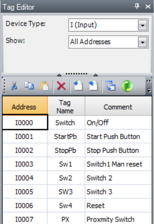


The picture above shows the overall work area of the Idec plc platform. On the view tab, you can choose what window to show up on the screen. On the left, you can see the tag editor to choose various types of registers such as input, output, memory, timer, a data register, and so on. On the Home tab, basic has the instruction used repeatedly, Advanced has the move, data comparison, arithmetic, boolean, shift and rotate, data conversion, and various programming tools and functions. At the very lower, You can see plc type FT1A-12, Data communication rates. On the info screen, you will see errors that occurred during the programs. Main Program is the are you will write the ladder logic. You will set up the type of plc, ways to control run/stop, memory, input types, device settings, passwords, calendar clock, and communication settings using the Configuration button.

In Figure 1, Rung 1 Line1: It has a NO (Normally Open) Contact Switch that turns on the Lamp. If the Switch is ON, the Lamp will turn. If the switch is off, the lamp will turn off.
Line 2 and 3 is a self-latching circuit or a holding relay. Stop push is NC (Normally Closed). When the Start push button is pressed, the output coil System Ready will be on, so that the System Ready contact will turn on. The system will be ready even when the start button is not on when the system is self latched.
Line 4 is an example of a set coil.
Line 5 and line 6 is an interlock circuits. When switch 2 is pressed and switch 3 is not pressed Green Light will turn on. When switch 2 is not pressed, and switch 3 is pressed, the Red light will turn on, saying the system is stopped.

In Figure 2 Rung 2, line 4 When the system is ready, the timer will start for 15 seconds. On line 3, when the switch is pressed AND if the 15-second timer is done, the motor will be in running.
On Rung 3, When the system is ready, the MOV function is used to move source one (S1) TC000 timer current value to Destination register(D1) D0000 Data Register zero. Rep represent repeat. 15 is moved to D0001, and Subtraction is performed using the SUB function. Source One S1 has selected Data Register D000, and D0000 is chosen for Source Two S2. The subtracted value is saved on Destination Register D1, (Data Register D0002).
D1 is the Destination Register.
D0000 is Data Register.

In figure 4, the Counter is used in the program, Manual or Auto reset of the counter can be performed. The current value of the counter (Source S1) is moved to data register D0000(Destination D1). The pulse of the proximity sensor will count up, and the preset is set to 5.
Auto-reset in the program is based on a 30-second timer.
Rung 3 has the count up and down counter which is often used in the parking lot to count cars.
The counter is mainly used for counting the parts in the production area in the plant. Counting the parts manufactured, bottles, and pizza are some of the examples of Counter applications.
Sensor (proximity, IR laser sensor, inductive, capacitive) is used to sense the parts for counting.

Rung 1 is an example of OR logic, either of the switches will turn the lamp.
Rung 2 is AND logic, both of the switch has to be pressed in order to run the motor
Line 4,5,6 is used for the blinking of the circuit based on the timer. (on and off delay timer)

Fig:-6
Light output is based on the timer for a different color lamp, stack light, tower light, and strobe light.
In the example above,
red light depends on 5 seconds timer,
yellow light depends on 3 seconds timer,
green light depends on a 7seconds sec timer.

The counter function is built using AND, SOTU (Single Output Up) Data Register comparison, and setting D0000 to zero once the preset is 10. The second line is used to show the rapid number changes if SOTU is not used. In line 4, LCAL is used for label calls to the subroutine.

SFR is used for shift register to forward direction R0, R1, R2 … R127.
In the above example, SFRN is used which is shift register reverse. ( R3, R2, R1, R0 )
The shift takes place on the rising edge of pulse or input I001 as shown.
MOV function is showing the data movement from one to other registers.
R is a shift register and is a single bit register, whereas the Destination register is a 16-bit register (word).
This paper is the exposure to basic instructions and functions in the Idec plc platform using ladder logic. In the next paper, I will be working on intermediate tutorials and Advanced projects in the near future. I hope you have enjoyed the paper and course on Geek Nepal YouTube Channel.
Please provide me feedback, and kindly subscribe to the channel “Geek Nepal”
Thank You.
Shuvash Aryal
22-May 2022
Sunday, 11am
https://www.facebook.com/geeknepal
No comments:
Post a Comment