https://www.linkedin.com/pulse/step-by-step-procedure-download-electronic-data-sheeteds-aryal
Monday, May 1, 2023

Thursday, April 27, 2023
Steps to create a Programmable Logic Controller(PLC) program from scratch in Cosesys Software while using ChatGPT as a resource tool.
Program a Plc from scratch in Codesys Platform while following steps created by ChatGPT
Steps to create a Programmable Logic Controller(PLC) program from scratch in Cosesys Software while using ChatGPT as a resource tool.
i. What are the steps to configure Wago_750_352 from scratch in Codesys software?
ii. what are EDS and GSD files?
iii. Where can you find EDS/GSD file?
iv. What are the steps to download eds file for Wago_750_352?
v. Search for Wago_750_352 and Wago_750_307 on the wago website.
vi. What are the steps to load an eds file in Codesys?
Basics of Codesys using ChatGPT
What is the task and scan cycle in codesys?
What is the periodic and cyclic task?
What is a first scan bit?
What is edge detection in codesys?
What is F_Trig and R_Trig in Codesys?
What are DUT and POU in codesys?
What are the differences between timer and counter?
What are the types of timers used in codesys?
What are the types of counters in codesys?
Write a codesys program using Initial Cycle Bit, F_Trig, R_Trig, DUT, POU, and different types of timers and counters.
Write a POU for a main program in plc for motor control.
Write a codesys DUT struct for a motor control system
What is the task and scan cycle in codesys?
In CODESYS, the task and scan cycle are two important concepts related to the execution of a program on a programmable logic controller (PLC). A task is a unit of work that the PLC executes in a fixed cycle time. Each task represents a set of program instructions that the PLC executes repeatedly at a specific rate. For example, a task might control a motor or monitor a sensor. In CODESYS, you can create multiple tasks with different cycle times to execute different parts of your program. On the other hand, the scan cycle is the time it takes for the PLC to complete one iteration of all the tasks in a program. During each scan cycle, the PLC executes each task in turn, based on the task's defined cycle time. Once all the tasks have been executed, the PLC starts a new scan cycle from the beginning. For example, if you have two tasks in your program, one with a cycle time of 10ms and the other with a cycle time of 100ms, the PLC would execute the first task ten times before executing the second task once. This process repeats in a continuous loop, forming the scan cycle. The task and scan cycle are important concepts to understand when programming a PLC in CODESYS, as they help you design and optimize your program's execution flow and performance.
What is the periodic and cyclic task?
In the context of real-time systems, a periodic task is a task that must be executed at a fixed time interval, while a cyclic task is a task that must be executed repeatedly, but not necessarily at a fixed time interval. A periodic task is typically used when a certain operation needs to be executed at a specific rate, such as controlling a motor or reading sensor data. The period of a periodic task is the time interval between two consecutive executions of the task, and it must be constant to ensure the system meets its timing requirements. The execution of a periodic task is triggered by a timer or an external event that occurs at a fixed interval. A cyclic task, on the other hand, is used when a certain operation needs to be executed repeatedly, but not necessarily at a fixed rate. The execution of a cyclic task is triggered by the completion of a previous execution or by an external event that occurs at a non-fixed interval. Cyclic tasks are often used for non-time-critical operations, such as updating the user interface or performing maintenance tasks. In summary, a periodic task must be executed at a fixed time interval, while a cyclic task must be executed repeatedly, but not necessarily at a fixed time interval. Both types of tasks are important in real-time systems, and their use depends on the specific requirements of the system being designed.
What is a first scan bit?
In the context of PLC programming, the "first scan bit" is a special bit that is used to indicate whether the program is running for the first time after being loaded or reset. This bit is often referred to as the "Power-Up Bit" or "Initial Cycle Bit." During the first scan of the PLC program, the first scan bit is set to a value of 1. This allows the program to perform any necessary initialization or setup routines that are required before the program can operate normally. For example, the first scan bit might be used to initialize memory locations, reset counters, or activate certain outputs. After the first scan is complete, the first scan bit is typically reset to a value of 0, and the program enters its normal operating mode. Subsequent scans of the program will not set the first scan bit to 1, as the program is now considered to be running normally. The use of the first scan bit is important because it allows the PLC program to perform any necessary initialization routines before the program starts normal operation. This ensures that the system operates reliably and consistently, even after a power outage or system reset.
What is edge detection in codesys?
In CODESYS, edge detection refers to the ability to detect a transition or change of state on a digital input signal. This transition can be from a low to a high state, or from a high to a low state. Edge detection is often used in industrial automation applications to trigger a specific action or operation when a signal changes state. For example, a sensor might generate a pulse signal when a product passes by on a conveyor belt. The edge detection function can be used to detect each pulse and count the number of products passing by. In CODESYS, edge detection can be implemented using ladder logic or function block diagrams. There are several different types of edge detection functions available, including rising edge detection, falling edge detection, and pulse detection. Rising edge detection is used to detect the transition from a low to a high state on a digital input signal. When a rising edge is detected, a corresponding output signal can be triggered to perform a specific action. Falling edge detection is used to detect the transition from a high to a low state on a digital input signal. When a falling edge is detected, a corresponding output signal can be triggered to perform a specific action. Pulse detection is used to detect the duration of a pulse on a digital input signal. When a pulse is detected, the duration of the pulse can be measured and used to trigger a corresponding output signal. Overall, edge detection is an important feature in CODESYS that allows industrial automation systems to respond to changes in input signals, and perform specific actions or operations based on those changes.
What is F_Trig and R_Trig in Codesys?
F_Trig and R_Trig are two types of edge detection functions available in CODESYS that are used to detect the rising and falling edges of a digital input signal, respectively. F_Trig (short for "positive edge trigger") is an edge detection function that is used to detect the rising edge of a digital input signal. When the input signal transitions from a low state to a high state, the F_Trig function generates a positive output pulse that can be used to trigger a specific action or operation. R_Trig (short for "negative edge trigger") is an edge detection function that is used to detect the falling edge of a digital input signal. When the input signal transitions from a high state to a low state, the R_Trig function generates a negative output pulse that can be used to trigger a specific action or operation. Both F_Trig and R_Trig functions are often used in industrial automation applications to trigger specific actions or operations when a signal changes state. For example, F_Trig might be used to detect the rising edge of a sensor signal indicating the arrival of a product, while R_Trig might be used to detect the falling edge of a signal indicating the departure of the same product. In CODESYS, both F_Trig and R_Trig functions can be easily implemented using ladder logic or function block diagrams and can be customized to meet the specific requirements of a particular application.
What are DUT and POU in codesys?
DUT and POU are two important concepts in CODESYS, which stands for "Device Under Test" and "Program Organization Unit," respectively. DUT refers to the physical device or system that is being tested or controlled using CODESYS. This device can be a PLC, a remote I/O module, a motor controller, or any other type of industrial automation equipment that is capable of communicating with CODESYS. In order to communicate with the DUT, CODESYS must have the appropriate communication interface or driver installed and configured. POU, on the other hand, refers to a logical unit within a CODESYS program that performs a specific function or set of functions. A POU can be thought of as a modular block of code that can be reused across multiple programs, making it easier to develop, test, and maintain complex automation systems. There are several types of POUs available in CODESYS, including: - Function: a POU that performs a specific calculation or operation and returns a value. - Function Block: a POU that performs a specific operation and can have internal variables and inputs/outputs. - Program: a POU that contains a sequence of instructions that are executed in order. - Global Variable List: a POU that defines global variables that can be accessed by other parts of the program. Overall, DUT and POU are two important concepts in CODESYS that are essential for developing and testing industrial automation systems. The ability to communicate with a DUT and to organize code into reusable POUs can significantly improve the efficiency, reliability, and maintainability of a CODESYS program.
What are the differences between a timer and a counter?
In industrial automation and control systems, timers and counters are both commonly used to monitor and control processes, but they serve different purposes and have different functions. Here are the main differences between timers and counters: 1. Function: A timer is used to measure a time interval or delay, while a counter is used to count the number of events or pulses that occur within a certain period of time. 2. Input: A timer usually has a single input, which is typically a signal that triggers the start of the timer. A counter, on the other hand, typically has one or more inputs that are used to count the number of events or pulses. 3. Output: A timer generates an output signal after a specified time interval has elapsed. The output can be used to trigger a specific action or operation, such as turning on a motor or activating a valve. A counter generates an output signal after a certain number of events or pulses have been counted. The output can be used to trigger a specific action or operation based on the count, such as stopping a conveyor belt after a certain number of products have passed through. 4. Types: There are several types of timers available, including on-delay, off-delay, pulse, and cyclic timers, among others. Each type has its own unique features and functions. Counters also come in various types, such as up counters, down counters, and preset counters, among others. 5. Usage: Timers are commonly used in applications where timing is critical, such as in manufacturing processes, traffic control systems, and HVAC systems. Counters are commonly used in applications where counting the number of events or pulses is important, such as in inventory control systems, production line monitoring, and quality control systems. Overall, timers and counters serve different functions and are used in different applications, but both are essential tools for monitoring and controlling industrial processes.
What are the types of timers used in codesys?
CODESYS supports several types of timers, each with its own unique features and functions. Here are some of the most common types of timers used in CODESYS: 1. On-Delay Timer (TON): An On-Delay Timer starts counting time when the input signal turns ON and generates an output signal after a preset time interval has elapsed. 2. Off-Delay Timer (TOF): An Off-Delay Timer starts counting time when the input signal turns OFF and generates an output signal after a preset time interval has elapsed. 3. Pulse Timer (TP): A Pulse Timer generates an output signal that lasts for a preset time interval each time the input signal turns ON. 4. Retentive Timer (TR): A Retentive Timer remembers the time interval that was last counted even after power loss or program restart. This feature is useful in applications where it is important to retain the timer value, such as in tracking machine uptime. 5. Cyclic Timer (TC): A Cyclic Timer generates an output signal that turns ON and OFF at a regular interval. This type of timer is useful in applications where a process needs to be repeated at regular intervals, such as in conveyor belt systems or material handling systems. 6. Watchdog Timer (WD): A Watchdog Timer is used to monitor the status of a program or device and generate an output signal if the program or device fails to respond within a preset time interval. This feature is useful in applications where system failure can have serious consequences, such as in safety-critical systems. Overall, the type of timer used in CODESYS depends on the specific requirements of the application. By choosing the appropriate timer type and configuring it correctly, developers can ensure that the automation system performs the required functions accurately and reliably.
What are the types of counters in codesys?
CODESYS supports several types of counters, each with its own unique features and functions. Here are some of the most common types of counters used in CODESYS: 1. Up Counter (CTU): An Up Counter increments a count value each time the input signal turns ON and generates an output signal when the count value reaches a preset value. 2. Down Counter (CTD): A Down Counter decrements a count value each time the input signal turns ON and generates an output signal when the count value reaches a preset value. 3. Up/Down Counter (CTUD): An Up/Down Counter can count up or down based on the input signal and generates an output signal when the count value reaches a preset value. 4. Ring Counter (CTR): A Ring Counter has multiple output signals that turn ON in a sequence based on the count value. This type of counter is useful in applications where a specific sequence of operations needs to be performed. 5. Shift Register (CTSR): A Shift Register stores a series of input signals in a register and shifts the register contents each time the input signal turns ON. This type of counter is useful in applications where a series of operations needs to be performed sequentially. 6. Pulse Counter (CTP): A Pulse Counter counts the number of input pulses that occur within a preset time interval and generates an output signal when the count value reaches a preset value. Overall, the type of counter used in CODESYS depends on the specific requirements of the application. By choosing the appropriate counter type and configuring it correctly, developers can ensure that the automation system performs the required functions accurately and reliably.
Write a codesys program using Initial Cycle Bit, F_Trig, R_Trig, DUT, POU, and different types of timers and counters.


PROGRAM MainPtogram
VAR InitialCycleBit: BOOL; InputSignal: BOOL; OutputSignal: BOOL; RisingEdge: BOOL; FallingEdge: BOOL; Counter: CTD; Timer: TON; END_VAR (* Program organization unit *) POU CounterReset VAR_INPUT Reset: BOOL; END_VAR VAR_OUTPUT END_VAR VAR InternalCounter: INT; END_VAR IF Reset THEN InternalCounter := 0; ELSE InternalCounter := InternalCounter + 1; END_IF END_POU (* Device under test *) DUT InputProcessing VAR_INPUT Input: BOOL; END_VAR VAR_OUTPUT Output: BOOL; END_VAR VAR RisingEdge: F_TRIG; FallingEdge: R_TRIG; END_VAR (* Rising edge detection *) RisingEdge(CLK := Input, Q => RisingEdge); (* Falling edge detection *) FallingEdge(CLK := Input, Q => FallingEdge); (* Output signal *) Output := RisingEdge.Q; END_DUT (* Main program *) InitialCycleBit := TRUE; Timer(IN := InputSignal, PT := T#10s, Q => OutputSignal); Counter(CU => RisingEdge.Q, CD => FallingEdge.Q, PV => 10, Q => Counter.Q); IF InitialCycleBit THEN (* Initialization code goes here *) InitialCycleBit := FALSE; END_IF (* Reset counter on rising edge of input signal *) CounterReset(Reset := RisingEdge.Q); (* Process input signal *) InputProcessing(Input := InputSignal, Output => OutputSignal); END_PROGRAM
Write a POU for a main program in plc for motor control.

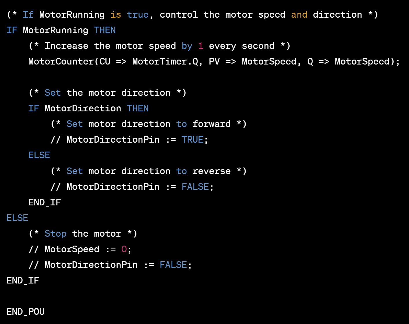
POU MotorControl VAR_INPUT StartMotor: BOOL; StopMotor: BOOL; MotorDirection: BOOL; MotorSpeed: INT; END_VAR VAR_OUTPUT MotorRunning: BOOL; END_VAR VAR MotorTimer: TON; MotorCounter: CTD; END_VAR (* If StartMotor is true and MotorRunning is false, start the motor *) IF StartMotor AND NOT MotorRunning THEN MotorRunning := TRUE; MotorTimer(IN := TRUE, PT := T#5s, Q => MotorRunning); END_IF (* If StopMotor is true and MotorRunning is true, stop the motor *) IF StopMotor AND MotorRunning THEN MotorRunning := FALSE; END_IF (* If MotorRunning is true, control the motor speed and direction *) IF MotorRunning THEN (* Increase the motor speed by 1 every second *) MotorCounter(CU => MotorTimer.Q, PV => MotorSpeed, Q => MotorSpeed); (* Set the motor direction *) IF MotorDirection THEN (* Set motor direction to forward *) // MotorDirectionPin := TRUE; ELSE (* Set motor direction to reverse *) // MotorDirectionPin := FALSE; END_IF ELSE (* Stop the motor *) // MotorSpeed := 0; // MotorDirectionPin := FALSE; END_IF END_POU
In this POU, there are four inputs:
- StartMotor: A boolean input that starts the motor when set to TRUE.
- StopMotor: A boolean input that stops the motor when set to TRUE.
- MotorDirection: A boolean input that sets the direction of the motor. If TRUE, the motor spins in one direction, and if FALSE, it spins in the opposite direction.
- MotorSpeed: An integer input that sets the speed of the motor.
There is one output:
- MotorRunning: A boolean output that indicates whether the motor is currently running or not.
The POU also contains two internal variables:
- MotorTimer: A timer that counts for 5 seconds when the motor is started. After 5 seconds, if the timer has not been reset, it sets MotorRunning to FALSE.
- MotorCounter: A counter that increments the MotorSpeed value by 1 every second while the motor is running.
The POU contains three main sections:
Start/Stop Logic: This section starts or stops the motor based on the inputs. If StartMotor is set to TRUE and MotorRunning is set to FALSE, the motor is started and MotorRunning is set to TRUE. If StopMotor is set to TRUE and MotorRunning is set to TRUE, the motor is stopped, and MotorRunning is set to FALSE.
Motor Speed and Direction: This section controls the speed and direction of the motor while it is running. If MotorRunning is set to TRUE, the MotorCounter increments the MotorSpeed value by 1 every second. The MotorDirection input sets the direction of the motor based on whether it is TRUE or FALSE.
Stop Timer: This section stops the motor after 5 seconds if the MotorTimer has not been reset. If MotorRunning is set to TRUE, the MotorTimer is reset, and the timer starts counting again. If the MotorTimer reaches 5 seconds and is not reset, it sets MotorRunning to FALSE, which stops the motor.
Again, this is just an example, and you may need to modify it based on your specific motor control application.
Write a codesys DUT struct for a motor control system

// Define a DUT struct for the motor control system // This struct contains inputs, outputs, and internal variables for the system DUT MotorControlSystem: STRUCT // Inputs StartMotor: BOOL; StopMotor: BOOL; MotorDirection: BOOL; MotorSpeed: INT; // Outputs MotorRunning: BOOL; // Internal variables MotorTimer: TON; MotorCounter: CTD; END_STRUCT
In this DUT struct, there are four inputs:
- StartMotor: A boolean input that starts the motor when set to TRUE.
- StopMotor: A boolean input that stops the motor when set to TRUE.
- MotorDirection: A boolean input that sets the direction of the motor. If TRUE, the motor spins in one direction, and if FALSE, it spins in the opposite direction.
- MotorSpeed: An integer input that sets the speed of the motor.
There is one output:
- MotorRunning: A boolean output that indicates whether the motor is currently running or not.
The DUT struct also contains two internal variables:
- MotorTimer: A timer that counts for 5 seconds when the motor is started. After 5 seconds, if the timer has not been reset, it sets MotorRunning to FALSE.
- MotorCounter: A counter that increments the MotorSpeed value by 1 every second while the motor is running.
You can use this DUT struct as a blueprint for implementing the motor control system in your CODESYS project.
Tuesday, April 25, 2023
2. PLC, HMI, DCS, & SCADA using ChatGPT
PLC, HMI, DCS, & SCADA
1. What is a Programmable Logic Controller (PLC)?
1.1Major PLC manufacturers
2. What is a Human Machine Interface (HMI)?
2.1Major HMI manufacturers
3. What is a DCS (Distributed Control System)?
3.1Major DCS manufacturers
4. what is a Supervisory Control and Data Acquisition (SCADA)?
5. What software is used to program a PLC device?
6. What software is used to program HMI screens?
7. What software is used to program DCS?
8. What software is used to program SCADA?
9. How are plc, dcs, hmi, and scada system interconnected?
10. What are the types of plc programming languages used today?
1. What is a Programmable Logic Controller (PLC)?
PLC stands for Programmable Logic Controller. It is a specialized computer used in industrial control systems to automate processes and machinery. PLCs are designed to be rugged and reliable in harsh industrial environments, and can be programmed to perform a wide variety of tasks, such as controlling the speed of a motor, monitoring the temperature of a furnace, or managing the flow of materials through a production line.
PLCs are typically programmed using a specialized programming language, such as ladder logic or function block diagram, and are often integrated with other industrial control devices, such as sensors, actuators, and human-machine interfaces (HMIs). They are widely used in manufacturing, automotive, aerospace, and other industries to increase efficiency, reduce downtime, and improve safety.
1.1Major PLC manufacturers
There are many manufacturers of PLCs, but some of the major players in the market include:
Siemens: A German company that produces a range of automation and control products, including PLCs. Siemens' SIMATIC series of PLCs are widely used in industrial automation.
Rockwell Automation: An American company that produces a range of automation and control products, including PLCs. Rockwell's Allen-Bradley series of PLCs are well known in the industry.
ABB: A Swiss-Swedish company that produces a range of products in the power and automation sectors, including PLCs. ABB's AC500 series of PLCs are popular in the industry.
Mitsubishi Electric: A Japanese company that produces a range of products in the automation and control sectors, including PLCs. Mitsubishi's MELSEC series of PLCs are widely used in industrial automation.
Schneider Electric: A French company that produces a range of products in the energy management and automation sectors, including PLCs. Schneider's Modicon series of PLCs are popular in the industry.
Omron: A Japanese company that produces a range of automation and control products, including PLCs. Omron's SYSMAC series of PLCs are widely used in industrial automation.
These are just a few examples of major PLC manufacturers, and there are many other companies that produce PLCs as well.
2.What is a Human Machine Interface (HMI)?
HMI stands for Human-Machine Interface. It is a device or software that allows an operator to interact with a machine, system, or process. The HMI serves as a bridge between the operator and the machine, providing a graphical interface that displays real-time information about the machine's status, and allows the operator to control the machine or process.
HMIs can take many different forms, including:
1. Touchscreens: These are the most common type of HMI, which allows the operator to interact with the machine using a touch screen interface.
2. Keyboards: Some HMIs use a keyboard interface for operator input.
3. Mouse: Some HMIs use a mouse interface for operator input.
4. Pushbuttons: Some HMIs use a push-button interface for operator input.
5. Software: Some HMIs are software-based, running on a computer and providing a graphical user interface.
HMIs are widely used in industrial automation, where they are used to control and monitor manufacturing processes, machines, and equipment. They can also be used in other applications, such as building automation, transportation systems, and medical equipment. HMIs are designed to be intuitive and easy to use, allowing operators to quickly and easily control and monitor complex processes.
2.1Major HMI manufacturers
There are several manufacturers of HMIs, but some of the major players in the market include:
1. Siemens: A German company that produces a range of automation and control products, including HMIs. Siemens' SIMATIC HMI series of products are widely used in industrial automation.
2. Rockwell Automation: An American company that produces a range of automation and control products, including HMIs. Rockwell's PanelView series of HMIs are well known in the industry.
3. Schneider Electric: A French company that produces a range of products in the energy management and automation sectors, including HMIs. Schneider's Magelis series of HMIs are popular in the industry.
4. ABB: A Swiss-Swedish company that produces a range of products in the power and automation sectors, including HMIs. ABB's CP600 series of HMIs are widely used in industrial automation.
5. Mitsubishi Electric: A Japanese company that produces a range of products in the automation and control sectors, including HMIs. Mitsubishi's GOT series of HMIs are popular in the industry.
6. Omron: A Japanese company that produces a range of automation and control products, including HMIs. Omron's NS series of HMIs are widely used in industrial automation.
These are just a few examples of major HMI manufacturers, and there are many other companies that produce HMIs as well.
3.What is a DCS (Distributed Control System)?
DCS stands for Distributed Control System. It is a type of industrial control system used to control and monitor complex processes, such as those found in chemical plants, power generation facilities, and manufacturing plants.
A DCS system consists of a network of controllers, sensors, actuators, and other devices, all connected to a central control room. The controllers are distributed throughout the plant, with each controller responsible for a specific area or process. The controllers communicate with each other and with the central control room to coordinate the overall operation of the plant.
DCS systems are designed to be highly reliable and scalable, and are capable of managing large, complex processes with thousands of control points. They provide real-time monitoring and control of process variables, such as temperature, pressure, flow rate, and chemical composition. DCS systems can also provide advanced control algorithms, such as model predictive control, to optimize process performance and improve efficiency.
DCS systems are often used in industries where safety and reliability are critical, such as chemical processing, oil and gas, and power generation. They are also used in other industries, such as manufacturing and food processing, where precise control of processes is important for maintaining quality and consistency.
3.1Major DCS manufacturers
There are several manufacturers of DCS systems, but some of the major players in the market include:
1. Emerson: An American company that produces a range of automation and control products, including DCS systems. Emerson's DeltaV series of DCS systems are widely used in industrial automation.
2. ABB: A Swiss-Swedish company that produces a range of products in the power and automation sectors, including DCS systems. ABB's Symphony Plus series of DCS systems are popular in the industry.
3. Siemens: A German company that produces a range of automation and control products, including DCS systems. Siemens' SIMATIC PCS 7 series of DCS systems are widely used in industrial automation.
4. Honeywell: An American company that produces a range of products in the automation and control sectors, including DCS systems. Honeywell's Experion series of DCS systems are popular in the industry.
5. Yokogawa: A Japanese company that produces a range of products in the automation and control sectors, including DCS systems. Yokogawa's CENTUM series of DCS systems are widely used in industrial automation.
These are just a few examples of major DCS manufacturers, and there are many other companies that produce DCS systems as well.
4.what is a Supervisoty Control and Data Acquition (SCADA)?
SCADA stands for Supervisory Control and Data Acquisition. It is a type of industrial control system used to monitor and control remote equipment and processes in real-time.
A SCADA system typically consists of a central computer or server, called a SCADA host, and one or more remote devices, called remote terminal units (RTUs) or programmable logic controllers (PLCs). The RTUs or PLCs are installed at remote sites, such as pipelines, electrical grids, water treatment plants, and other critical infrastructure, and are used to collect data and control equipment.
The SCADA host collects and analyzes data from the RTUs or PLCs, and provides operators with a graphical user interface for monitoring and controlling the remote equipment and processes. SCADA systems are designed to be highly reliable and secure, and can operate over large distances using various communication protocols, such as Ethernet, Modbus, and DNP3.
SCADA systems are used in a variety of industries, including oil and gas, water treatment, power generation, manufacturing, and transportation. They are often used in applications where remote monitoring and control are required, such as in oil and gas pipelines, electrical grids, and transportation networks. SCADA systems can help improve efficiency, increase safety, and reduce downtime and maintenance costs.
5.What softwares are used to program a PLC device?
There are several software tools used to program PLC devices, including:
1. Siemens TIA Portal: This software suite is used to program Siemens PLCs, including the S7-1200, S7-1500, and S7-300/400 series.
2. Rockwell Studio 5000: This software suite is used to program Rockwell Automation PLCs, including the ControlLogix, CompactLogix, and FlexLogix series.
3. Schneider Electric Unity Pro: This software suite is used to program Schneider Electric PLCs, including the M340, M580, and Quantum series.
4. Mitsubishi GX Works: This software suite is used to program Mitsubishi Electric PLCs, including the FX, Q, and L series.
5. Omron CX-One: This software suite is used to program Omron PLCs, including the CP1, CJ1, and CS1 series.
These are just a few examples of software tools used to program PLC devices, and there are many other options available on the market. The choice of software typically depends on the specific brand and model of PLC being used, as well as the requirements of the application being developed.
6.What softwares are used to program HMI screens?
There are several software tools used to program HMI screens, including:
1. Rockwell FactoryTalk View: This software suite is used to program Rockwell Automation HMIs, including the PanelView and PanelView Plus series.
2. Siemens WinCC: This software suite is used to program Siemens HMIs, including the Comfort Panels, Basic Panels, and Mobile Panels.
3. Schneider Electric Vijeo Designer: This software suite is used to program Schneider Electric HMIs, including the Magelis series.
4. Beijer Electronics iX Developer: This software suite is used to program Beijer Electronics HMIs, including the X2 and iX series.
5. Red Lion Crimson: This software suite is used to program Red Lion HMIs, including the Graphite and G3 series.
These are just a few examples of software tools used to program HMI screens, and there are many other options available on the market. The choice of software typically depends on the specific brand and model of HMI being used, as well as the requirements of the application being developed.
7.What softwares are used to program DCS?
There are several software tools used to program DCS (Distributed Control System) devices, including:
1. ABB 800xA: This software suite is used to program ABB DCS systems, including the 800xA and Advant Master series.
2. Emerson DeltaV: This software suite is used to program Emerson DCS systems, including the DeltaV series.
3. Siemens PCS 7: This software suite is used to program Siemens DCS systems, including the SIMATIC PCS 7 series.
4. Honeywell Experion: This software suite is used to program Honeywell DCS systems, including the Experion PKS and TDC series.
5. Yokogawa CENTUM VP: This software suite is used to program Yokogawa DCS systems, including the CENTUM VP series.
These are just a few examples of software tools used to program DCS devices, and there are many other options available on the market. The choice of software typically depends on the specific brand and model of DCS being used, as well as the requirements of the application being developed.
8.What software are used to program SCADA?
There are several software tools used to program SCADA (Supervisory Control and Data Acquisition) systems, including:
1. Inductive Automation Ignition: This software suite is used to program SCADA systems and includes features such as real-time monitoring, alarming, and reporting.
2. Wonderware System Platform: This software suite is used to program SCADA systems and includes features such as visualization, data analysis, and real-time control.
3. GE Digital iFIX: This software suite is used to program SCADA systems and includes features such as alarm management, historical data collection, and real-time control.
4. Schneider Electric EcoStruxure: This software suite is used to program SCADA systems and includes features such as remote monitoring, control, and optimization.
5. Siemens WinCC: This software suite is used to program SCADA systems and includes features such as visualization, alarm management, and real-time control.
These are just a few examples of software tools used to program SCADA systems, and there are many other options available on the market. The choice of software typically depends on the specific brand and model of SCADA system being used, as well as the requirements of the application being developed.
9.How are plc, dcs, hmi and scada system inter connected?
PLC, DCS, HMI, and SCADA systems can be interconnected in various ways to form a complete automation system that can efficiently control and monitor industrial processes. Here are a few examples of how these systems can be interconnected:
1. PLC and HMI: The PLC is programmed to control the process, while the HMI provides a graphical user interface for the operator to view and interact with the process. The HMI communicates with the PLC to provide real-time data about the process, and the PLC sends control signals to the process based on the operator's input through the HMI.
2. DCS and SCADA: The DCS system controls the entire plant, while the SCADA system is used for remote monitoring and control. The DCS system communicates with the SCADA system to provide real-time data about the plant, and the SCADA system allows the operator to view and control the plant from a remote location.
3. PLC and DCS: The PLC is used to control a specific part of the process, while the DCS system is used to control the entire plant. The PLC communicates with the DCS system to provide real-time data about the process, and the DCS system sends control signals to the PLC based on the process requirements.
4. HMI and SCADA: The HMI provides a graphical user interface for the operator to view and control the process, while the SCADA system is used for remote monitoring and control. The HMI communicates with the SCADA system to provide real-time data about the process, and the SCADA system allows the operator to view and control the process from a remote location.
In general, PLCs and HMIs are used to control and monitor a specific part of the process, while DCS and SCADA systems are used to control and monitor the entire plant. These systems can be interconnected in various ways to form a complete automation system that provides efficient and reliable control and monitoring of industrial processes.
10.What are types of plc programming languages used today?
There are several types of PLC programming languages used today, each with its own syntax and structure. Here are some of the most common types of PLC programming languages:
1. Ladder Logic (LAD): Ladder Logic is a graphical programming language that represents logic operations with symbols, such as "rungs" of a ladder. It is easy to learn and widely used in many industries.
2. Structured Text (ST): Structured Text is a high-level text-based programming language that resembles Pascal or C programming language syntax. It allows for complex programming logic and is used for more advanced control applications.
3. Function Block Diagram (FBD): Function Block Diagram is a graphical programming language that allows users to create function blocks, which are reusable sections of code that perform specific tasks. It is commonly used for complex control systems.
4. Sequential Function Chart (SFC): Sequential Function Chart is a graphical programming language that represents a control program as a series of steps. It is often used for batch processing and complex control systems.
5. Instruction List (IL): Instruction List is a low-level text-based programming language that uses mnemonic codes to represent machine instructions. It is similar to assembly language programming and is used for very specific control applications.
The choice of programming language often depends on the specific application requirements, the familiarity of the programmer with the language, and the programming software available for the PLC. Many modern PLC programming software tools support multiple programming languages, allowing programmers to use the language that best suits their needs.
Subscribe to:
Posts (Atom)